JTK – Notes and Ramblings Things we have found …

12/30/2022

Shades – a start

Filed under: General,Home Automation — taing @ 12:21 pm

I decide to try the Home Depot Decorator Collection Shades. These have a motorize option that is controllable via Bluetooth using either their remote or a smartphone app (Android or iOS). The motor kit (FAQ) is pretty simple to install.

Unfortunately, there is no documented integration API. I found a few discussions online:

I am waiting to try the Bluetooth clone/copy MAC address scheme.

I did follow the shelly1 option as far as getting the required wires added. Simply add wires to the BTN (red wire on ribbon cable) and +W pins –

.

I have not yet completed the shelly1 connection or the integration into Openhab.

Yoda Speaks

Filed under: Arduino,General — taing @ 11:49 am

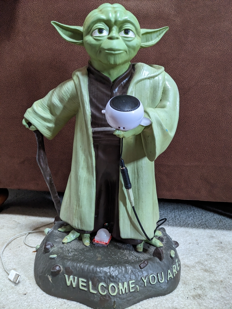
It was finally time to put the Sparkfun Papa Soundie to work. The Sparkfun hook-up guide provides most of the details – a 3.3v ATmega328P paired with the VLSI‘s VS1000D audio codec IC. They have created an Arduino library to control the VS1000D. This can be downloaded as a zip (archive version).

For the really adventurous there is VSIDE from VLSI to reprogram the firmware in the VS1000D – there are application examples, source code samples and additional PC tools available. We archived a copy of the VS1000D programmers guide.

I supplemented the Papa Soundie with a small speaker and a PIR motion sensor, Sparkfun’s OpenPIR. The sensor is based around the NCS36000 PIR controller and will work with 3v to 5.75v. Sparkfun has created a hook-up guide, also.

Audacity made quick work of converting a few .wav and .mp3 sound clips of Yoda’s voice to the preferred Ogg Vorbis / .ogg format. The preinstalled firmware on the VS1000D wants to find files in either .ogg or .wav format on the microSD card. The files should be named AUDIOxx.OGG or FILESxx.WAV (xx is 00 thru 31). Unfortunately, you need to start with 00 and not skip any slots.

I based my project on the Hardware Example Project from the Sparkfun Hook-up Guide. I removed the code for the servo and added code to prevent immediate re-triggering and to randomly select the file to play. The random selection is configured not to repeat a file until all have played – card deal style.

#include "SparkFun_PapaSoundie.h"

  int motionStatusOld = LOW;
  int motionStatus = LOW;
  int sounds[] = {1, 2, 3, 4, 5};
  int len = 5;

#define PIR_DOUT 9 

PapaSoundie sfx = PapaSoundie();

void setup() {
  Serial.begin(115200);  // Serial is used to view Analog out
  // Analog and digital pins should both be set as inputs (not actually necessary for Analog):
  pinMode(PIR_DOUT, INPUT);
  Serial.println("Getting ready");
  sfx.begin();
}

void loop() {
  int rnd;
  int choice;
  motionStatusOld = motionStatus;
  motionStatus = digitalRead(PIR_DOUT);
  if (motionStatus == HIGH && motionStatus != motionStatusOld) {
    if (len > 1) {
      rnd = random(len);
      choice = sounds[rnd];
      sounds[rnd] = sounds[len-1];
      len = len - 1;
    } else {
      choice = sounds[0];
      len = 5;
        for ( int i = 0; i < len; ++i ){
          sounds[i] = i+1;
        }      
    }
    
    Serial.println(choice);
    
    
    sfx.playFileNumber(choice);
    delay(1000);
  }
}

The wiring is very basic – 5vdc and ground in on the VIN and GND pins, 3.3vdc and ground out to the sensor from the 3.3v and GND pins and the output of the sensor to pin D9.

Keep in mind the sensor does require a bit of time after power-up before being active. The LED on the sensor PCB will blink slowly during start-up. Once up and running the LED will indicate motion.

I think the next step might be to add an LED. Possibly the Sparkfun RGB addressable thru hole version. This is a thru hole 8mm version of the typical WS2812. Three are details in their WS2812 Guide. Adafruit has a very nice Arduino library for the WS2812.

Sound activated Yoda

12/29/2022

Sonoff S31 and B1

Filed under: General,Home Automation — taing @ 9:47 pm

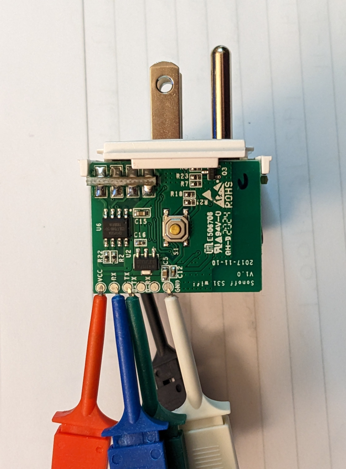
Sadly, I never posted any notes on the Sonoff products. Long ago I ordered a set of S31 outlets and B1 lamps. Both of which I reflashed with espurna. The notes on how to flash tasmota are helpful here, too. I found a quick tutorial on flashing with a Raspberry Pi in their docs. In todays world you might need to use pip3 instead of pip to install esptool. Tinkerman has posted lots of great details for the S31.

NEVER connect the S31 to mains power when flashing. For the S31 the connections to the Pi are very simpleSonoff S31 connections Raspberry Pi connections:

    S31 Pin - Pi Pin
    Vcc     - #1 (3.3vdc) - do not connect yet
    RX      - #8 (TX)
    TX      - #10 (RX)
    GND     - #39 (Ground)

Once you have the wiring ready you can setup the Pi – make sure you have esptool installed. If not sudo pip3 install esptool should handle it. You can then use raspi-config -> InterfaceOptions -> Serial to say No to shell on the serial port and Yes to Serial hardware.

The S31 will enter loader mode if you hold down the button, connect Vcc and continue holding the button for 10 seconds. You are now ready to actually flash the device(I was using an older Pi 2):

esptool.py --port /dev/ttyAMA0 erase_flash
esptool.py --port /dev/ttyAMA0 write_flash -fm dout 0x0 /path/to/downloaded/image

If you are using a Pi 3 or 4 replace ttyAMA0 with ttyS0.

The bad news is the Sonoff B1 is no longer made and their replacement uses a different chip and is not re-flashable. For the B1 lamps I have MQTT control after reflashing is awesome. MQTT make the integration with Openhab super easy. If you happen to come across these at a good price then the flashing instructions at the Tasmota site are very helpful.

5/30/2022

Updates and a new RTL-SDR

Filed under: Home Automation,RTL-SDR — Tags: , — taing @ 5:53 pm

Time for some updates and to add the new RadarBox 978 MHz radio. The system is still Raspian based on Buster. Keep in mind the initially the RTL-SDR for ads-b data is device 1(RTL2832U) and the weather station data is on device 0(RTL2838UHIDIR).

I’ll take these things somewhat in the order originally installed. readsb(our option over the other dump1090 alternatives) can be updated using the same bash script that was used for the install. Be sure to keep your current /etc/default/readsb file.

sudo bash -c "$(wget -O - https://github.com/wiedehopf/adsb-scripts/raw/master/readsb-install.sh)"

tar1090(an improved web page to display your data) can be updated much like readsb using the original install script.

sudo bash -c "$(wget -nv -O - https://github.com/wiedehopf/tar1090/raw/master/install.sh)"

FlightAware is updated from your site’s My ADS-B Stats page. Once on your stats page, click on the gear and choose update.

Instruction for updating ADSBexchange can be found on their page. The short answer is a bit of command line:

ccurl -L -o /tmp/axstats.sh https://www.adsbexchange.com/stats.sh
sudo bash /tmp/axupdate.sh

FlightRadar24 should update from its repository with apt-get.

Updating graphs1090 is once again as simple as running the original install script again.

sudo bash -c "$(curl -L -o - https://github.com/wiedehopf/graphs1090/raw/master/install.sh)"

I found nothing on the RadarBox site regarding updates so I left it alone for now.

At this point everything should work as before with ADSBexchange, FlightAware, FlightRadar24 and RadarBox all still working.

Now it is time to update the serial numbers on the dongles, add the new 978MHz dongle and update the existing config files to work with that info. I used the notes at dump978-fa install instructions to set the serial numbers of the dongles. The RadarBox flightstick instructions also show how to update the serial numbers. I also updated /etc/rtl_433/rtl_433.conf to point to my new device with serial number 433(rtl_eeprom -s 433) for the LaCrosse Weather Station.

I then continued to follow the dump978 instructions.

sudo apt update
sudo apt install -y dump978-fa
sudo sed -i -e 's/RECEIVER_OPTIONS.*/RECEIVER_OPTIONS="--sdr-gain 43.9 --sdr driver=rtlsdr,serial=978 --format CS8"/' /etc/default/dump978-fa
sudo systemctl restart dump978-fa

Then a quick install of the ADS-B exchange UAT/978 feed client following the github instructions.

sudo bash -c "$(wget -q -O - https://raw.githubusercontent.com/adsbxchange/adsbexchange-978/master/install.sh)"

A quick edit to /etc/rbfeeder.ini to enable UAT/978MHz and a reboot and we are in business.

http://<pi-ip>/tar1090/
http://<pi-ip>/ax978/
http://<pi-ip>/radar/
http://<pi-ip>/graphs1090/
http://<pi-ip>:8754/

https://flightaware.com/adsb/stats/user/xxx
https://www.adsbexchange.com/myip/
https://www.flightradar24.com/account/feed-stats/?id=xxxxx
https://www.radarbox.com/stations/xxxxxx

Updating Pi –

Filed under: General,Router/PC Config — taing @ 2:06 pm

After being away from things for a bit, it was time to update several of the Pis but I was met with an unfortunate error wen executing sudo apt-get update:

E: Repository 'http://raspbian.raspberrypi.org/raspbian buster InRelease' changed its 'Suite' value from 'stable' to 'oldstable'
N: This must be accepted explicitly before updates for this repository can be applied. See apt-secure(8) manpage for details.
E: Repository 'http://archive.raspberrypi.org/debian buster InRelease' changed its 'Suite' value from 'testing' to 'oldstable'
N: This must be accepted explicitly before updates for this repository can be applied. See apt-secure(8) manpage for details.

After consulting the oracle I found an article that had a solution. Turns out that Buster moved to “oldstable” after Bullseye became the current “stable”. The simple solution is:

sudo apt-get update --allow-releaseinfo-change

This will update the appropriate configuration setting for atp-get to allow thing to continue.

12/30/2021

Lua and encryption

Filed under: General — taing @ 2:07 pm

Several times I’ve gone looking for a bit of Lua to do some encryption. For most of these cases I need to have something reversible – meaning I need to recover the original text not just prove it matches with a hash…

This time I have a few candidates:

First is Bruce Schneier’s Solitaire algorithm. I found a Lua implementation. Solitaire is unfortunately limited to the 26 uppercase letters.

Then I found a pair of AES implementations – first and second. These come from the same guy on github but the first one seems a bit more standalone. From what I read these are both pretty slow.

I then stumbled upon https://github.com/philanc/plc where there are several algorithms implemented in pure Lua. morus sounds good and is described as very fast but requires 64 bit integers.

I also found a small simple algorithm that seems to be a good fit. One word of caution here is the results from this will be quite different if you only have 32 bit Lua. I’m not sure what impact 32 bit only has on the security of the method.

12/29/2020

DDC and CEC and more TV control

Filed under: Home Automation — taing @ 10:54 am

The quest to control the TVs and monitors continues. One promising option is DDC/C control. I was able to install ddcutil: sudo apt-get install ddcutil. For the older Acer units with Nvidia Ion graphics I was able to retrieve EDID but was unable to detect DDC.

The ddcutil website suggested adding the following in /etc/modprobe.d/nvidia-ddc :

options nvidia NVreg_RegistryDwords=RMUseSwI2c=0x01;RMI2cSpeed=100

I found that for the GeForce GT 710 machine this helped but not for the Acer with Ion graphics. Unfortunately, the Samsung T24C550 TV only seems to support a limits subset of DDC commands.

Next up was ddccontrol. After installing, it wasn’t able to detect DDC on the Acer with Ion but was more successful of the GeForce system. Unfortunately, there was no entry for the Samsung in the ddccontrol database so only generic commands appear to be available.

It is worth noting that even on the GeForce system once the monitor went to sleep it wasn’t detected at all by either ddcutil or ddccontrol.

Further notes on using ddcutil without being root can be found at https://frdmtoplay.com/using-ddccontrol-as-a-non-root-user/#:~:text=ddcutil%20is%20a%20CLI%20based,is%20not%20’officially’%20supported. This really comes down to adding users to the i2cusers group.

CEC

CEC is another option for controlling HDMI devices. While CEC can be used with a variety of devices it is especially useful on the Raspberry Pi. Again, unfortunately it is not supported by most Nvidia cards but is reported to work with the Nvidia Shield.

Your first step will be to install cec-utils: sudo apt-get install cec-utils. Hopefully a scan will turn up your device.

 echo "scan" | cec-client -s -d 1

If it does not it is worth looking into cec-util from the v4l-utils package. You may find to need to install/create the drivers for /dev/cec0.

For my Samsung, CEC was not enabled by default. Samsung refers to CEC as Anynet+. It can be enabled in the Service Menu. To enter the service menu, with the power to the TV off press MUTE 1 8 2 POWER quickly on the remote. Other Samsung units use INFO MENU MUTE POWER for the service menu.

I found some good info on using Raspberry Pi with CEC and a variety of devices at https://www.raspberrypi.org/forums/viewtopic.php?f=35&t=15593&p=158409&hilit=cec_client#p158409.

An no discussion of using CEC would be complete without mentioning CEC-O-Matic. This website allows you to “build your own” CEC commands.

Samsung – In Depth

There is lots of in depth info on Samsung TVs and firmware at https://wiki.samygo.tv/index.php?title=This_is_the_first_document_you_have_to_read.

Vizio Smartcast

If you have a Vizio with Smartcast there is a bit of detective work shown on github.

12/20/2020

Roku Remote Control

Filed under: General,Home Automation,RTL-SDR — taing @ 10:36 pm

Back in April I mentioned adding some Roku remote control. At this point I’m thinking more javascript than Python.

Roku has a good External Control Protocol reference online.

Sending commands

Unfortunately, the Roku API will not accept Cross Origin Request. This is not an issue if communicating from Node or Python but from the browser using xhr or fetch() you will get CORS errors. When sending POST for button presses you don’t care about the response for a “mode:’no-cors’ ” will work.

let resp = await fetch("http://roku-ip:8060/keypress/play", {method:'POST', mode:'no-cors'})

For the GET for status from the browser one option is a “proxy” add the “Access-Control-Allow-Origin” header. Borrowing the idea from https://medium.com/gitignore/building-a-roku-remote-web-app-1c0db0056be4 we set our Apache web server.

sudo pico /etc/apache2/apache2.conf to edit the config file and add the following lines:

<Location /roku>
    ProxyPass "http://roku-ip:8060/"
    ProxyPassReverse "/" 
    Header add "Access-Control-Allow-Origin" "*"
</Location>

You will need to have several modules loaded in Apache for this to work: headers and proxy_http. This can be done with:

sudo a2enmod proxy_http
sudo a2enmod headers
sudo systemctl restart apache2

Deep Links

A very important link for launching directly into netflix content is https://unogs.com/search/. From this site you can find the contentid for much of the netflix content.

This allows for directly linking to content with something like:

curl -d '' "http://roku-ip:8060/launch/12?contentid=70136120&mediatype=series"

This is a simple POST to the URL with no body.

The folks at unofficial Netflix online Global Search also provide an API.

12/13/2020

IR Blaster

Filed under: General,Home Automation,RTL-SDR — taing @ 3:30 pm

We get started with the Sparkfun WRL-15031. The hook-up guide is a good place to start. I am using the  IR Controller ESP8266 firmware.

I don’t have PlatformIO installed so I used the standard Arduino IDE. This was my first time with the ESP8266 so I needed to add the ESP8266 Arduino Core. In the current Arduino IDE this can be done by adding https://arduino.esp8266.com/stable/package_esp8266com_index.json to  the File>Preferences>Additional Boards Manager URLs field of the Arduino IDE. Then using the Board Manager from the Tools > Board menu you can install the esp8266 platform.

Once you have the IDE installed and the board set to Generic ESP8266 you need to make sure you have some libraries installed. ESP8266WebServer, ESP8266WiFi and WiFiManager but you may need to install ArduinoJson, Time and IRremoteESP8266.

It’s time to load the sketch, compile and upload.

The key here is to make sure you set the IO pin definitions correctly.

const int pinr1 = 13; // Receiving pin
const int pins1 = 4; // Transmitting preset 1
const int pins2 = 12; // Transmitting preset 2
const int pins3 = 12; // Transmitting preset 3
const int pins4 = 12; // Transmitting preset 4
const int configpin = 0; // Reset Pin
const int ledpin = 5;

I changed getExternalIP = false; and removed the user_id related and Alex integration code. I set ntpServerName to my internal NTP server. I changed the ntp sync time from 5 minutes to 12 hours near the end of the setup() function: setSyncInterval(43200);.

Once the code is compiled and loaded some testing is needed. On the initial run the ESP will be in AP mode with a SSID of IR Controller Configuration. You can connect and set access point info, hostname, static IP, subnet mask, port, default gateway and passcode.

Once you’re able to connect it is time to find some IR codes. There is a bit of good info in the Tasmota IR page. I found Sony DVD player remotes and some of the IR controlled LED votive candles. There is also good info for Samsung and Vizio TVs online. The codes from http://remotecentral.com often need to be manipulated before they are compatible with the ESP IR library. I created a Excel spreadsheet with worksheets for Vizio, Sony and Samsung.

Once we have the codes we can start controlling things from the web. For example:

http://someip:port/msg=msg?code=E0E040BF:SAMSUNG:32&pass=1234&simple=1

will send a power on/off command of 32 bits in SAMSUNG format. After testing a bit of this I created a simple webpage to send a variety of codes.

There is more Arduino IR blaster info at Ken Shirriff’s blogpost 1 and post 2. For more info on Sony codes refer to https://www.sbprojects.net/knowledge/ir/sirc.php and http://www.hifi-remote.com/sony/.

For the record: Toshiba remote: SE-R0047, Vivio Remote unmarked, Sony Remote RMT-B119A, JVC Remote: RM-S212U.

12/5/2020

screen at startup

Filed under: General,Home Automation,RTL-SDR — taing @ 11:33 pm

Sometimes it would be nice to have screen start a detached session at start-up. This isn’t complicated. There are two steps. The first is to create a script to be run in the detached session and make it executable. We’ll call it start.sh.

pico start.sh
chmod +x start.sh

The second is to edit /etc/rc.local to have the script run inside screen at start-up. Add the following line before the exit 0 line.

su - pi -c "screen -dm -S pistartup ~/start.sh"

That’s all there is to it. I found notes on this at https://coderwall.com/p/quflrg/run-a-script-on-startup-in-a-detached-screen-on-a-raspberry-pi.

12/4/2020

More Flight tracking – adding RadarBox

Filed under: General,RTL-SDR — Tags: , — taing @ 5:55 pm

Radarbox.com is another flight tracking site similar to FlightAware, ADSB-Exchange and FR24. Instructions for feeding to Radarbox can be found at https://www.radarbox.com/sharing-data. Like most of the similar sites, feeding will get you an upgraded account for free. If you are already feeding others it is as simple as downloading and running a bash script.

Once you download and run the script a new repo will be added and their custom feeder app will be installed. Once their feeder starts running you can use sudo rbfeeder --showkey to see what your “key” is. A quick visit to the Radarbox website to create an account then “claim” your system at http://radarbox.com/raspberry-pi/claim and you are good to go.

10/8/2020

Windows 10 and Iomega Floppy Plus

Filed under: General — taing @ 9:58 am

The Iomega Floppy Plus has been around for quite a while. It has CompactFlash and SD card slots in addition to being a 3.5″ floppy drive. When first plugged into a Windows 10 machine the CF and SD slots appear as drive letters. The Floppy remains silent and does not appear in the drive list.

You need to install drivers. Fortunately, while there are no official drivers from Iomega, there are drivers that work.

From Device Manager:

  • Select the X1DE-USB device from the Other Devices list.
  • Right-Click to Update Driver.
  • Browse My Computer for Driver Software.
  • Let me pick from a list of device drivers on my computer
  • Show All Devices
  • Manufacturer = NEC Systems / Model = NEC USB Floppy
  • Acknowledge the warningthat Windows can’t verify this is the right driver.

The floppy drive should work now. Refer to https://www.techgeekandmore.com/getting-the-iomega-usb-floppy-drive-working/ for a version of these instructions with screenshots.

« Newer PostsOlder Posts »

Powered by WordPress