JTK – Notes and Ramblings Things we have found …

1/25/2023

Mighty Mule and LaCrosse Update

Filed under: General,Home Automation,RTL-SDR — taing @ 4:45 pm

It turns out there is another Mighty Mule Driveway Alarm somewhere in the neighborhood so the config from our previous article needed to be updated. The other signal is weak but it triggers frequently and requires the config to be a bit more sophisticated. The first step was to update the rtl_433.conf file to send the MQTT messages as a JSON packet:

output json
output mqtt://broker_ip_address,events=rtl_433/garage[/model]

The result looks something like(after I prettied it up with a bit of formatting):

rtl_433/garage/MightyMule-FM231 {
	"time":"2023-01-24 18:37:05.994411",
	"model":"MightyMule-FM231",
	"count":1,
	"num_rows":1,
	"len":9,
	"data":"ff8",
	"battery_ok":"0",
	"id":15,
	"motion":"true",
	"mod":"ASK",
	"freq":433.89011,
	"rssi":-9.5411,
	"snr":12.69084,
	"noise":-22.2319
}

It’s all the same data but in one message. The Openhab config gets changed to have a String Channel for the MQTT JSON packet, an String Item linked to this and two additional String Items a new rule will manipulate. The rule checks the if the id matches our unit and then updates the appropriate items. The id is set on the transmitter and receiver with the dip switches. The rule is very basic but it does the job:

rule "Driveway Alarm" when
  Item Mighty_Mule_JSON received update
then
  var jsonval = Mighty_Mule_JSON.state.toString
  var id = transform("JSONPATH", "$.id", jsonval)
  var time = transform("JSONPATH", "$.time", jsonval)
  if (id == "5") {
    MightyMule_Driveway_Motion.postUpdate("ON")
    MightyMule_Driveway_Motion_Change.postUpdate(time)
  }
end

Changing the rtl_433 MQTT output to be JSON also required updating the channels for the LaCrosse Weather station. Previously the Generic MQTT Thing had channels for individual MQTT messages for temperature, humidity, wind speed and wind direction. Now the JSON messages from the weather station require the channel to have a JSONPATH transformation. The weather station will send two messages, one with temperature and humidity and one with wind speed and direction:

rtl_433/garage/LaCrosse-TX141W {
	"time":"2023-01-24 18:09:36.626950",
	"protocol":73,
	"model":"LaCrosse-TX141W",
	"id":149742,
	"channel":0,
	"battery_ok":1,
	"temperature_C":-0.8,
	"humidity":74,
	"test":0,
	"mic":"CRC",
	"mod":"ASK",
	"freq":433.87334,
	"rssi":-0.135693,
	"snr":22.09624,
	"noise":-22.2319
}

rtl_433/garage/LaCrosse-TX141W {
	"time":"2023-01-24 18:09:36.626950",
	"protocol":73,
	"model":"LaCrosse-TX141W",
	"id":149742,
	"channel":0,
	"battery_ok":1,
	"wind_avg_km_h":4.5,
	"wind_dir_deg":139,
	"test":0,
	"mic":"CRC",
	"mod":"ASK",
	"freq":433.87334,
	"rssi":-0.135693,
	"snr":22.09624,
	"noise":-22.2319
}

A MQTT channel with a topic of rtl_433/garage/LaCrosse-TX141W will receive both messages. The trick is in the JSONPATH transformation. To extract temperature, for example, use JSONPATH:$.temperature_C. This means there are four channels with the same MQTT topic and different JSONPATH transformations. The log file will get warnings that you can’t extract wind speed from the temp/humidity message or temp/humidity from the wind message.

NOTE: Our LaCrosse S81120-INT includes the LaCrosse TX145WSDTH which sends messages as LaCrosse-TX141W.

?

12/30/2022

Shades – a start

Filed under: General,Home Automation — taing @ 12:21 pm

I decide to try the Home Depot Decorator Collection Shades. These have a motorize option that is controllable via Bluetooth using either their remote or a smartphone app (Android or iOS). The motor kit (FAQ) is pretty simple to install.

Unfortunately, there is no documented integration API. I found a few discussions online:

I am waiting to try the Bluetooth clone/copy MAC address scheme.

I did follow the shelly1 option as far as getting the required wires added. Simply add wires to the BTN (red wire on ribbon cable) and +W pins –

.

I have not yet completed the shelly1 connection or the integration into Openhab.

12/29/2022

Sonoff S31 and B1

Filed under: General,Home Automation — taing @ 9:47 pm

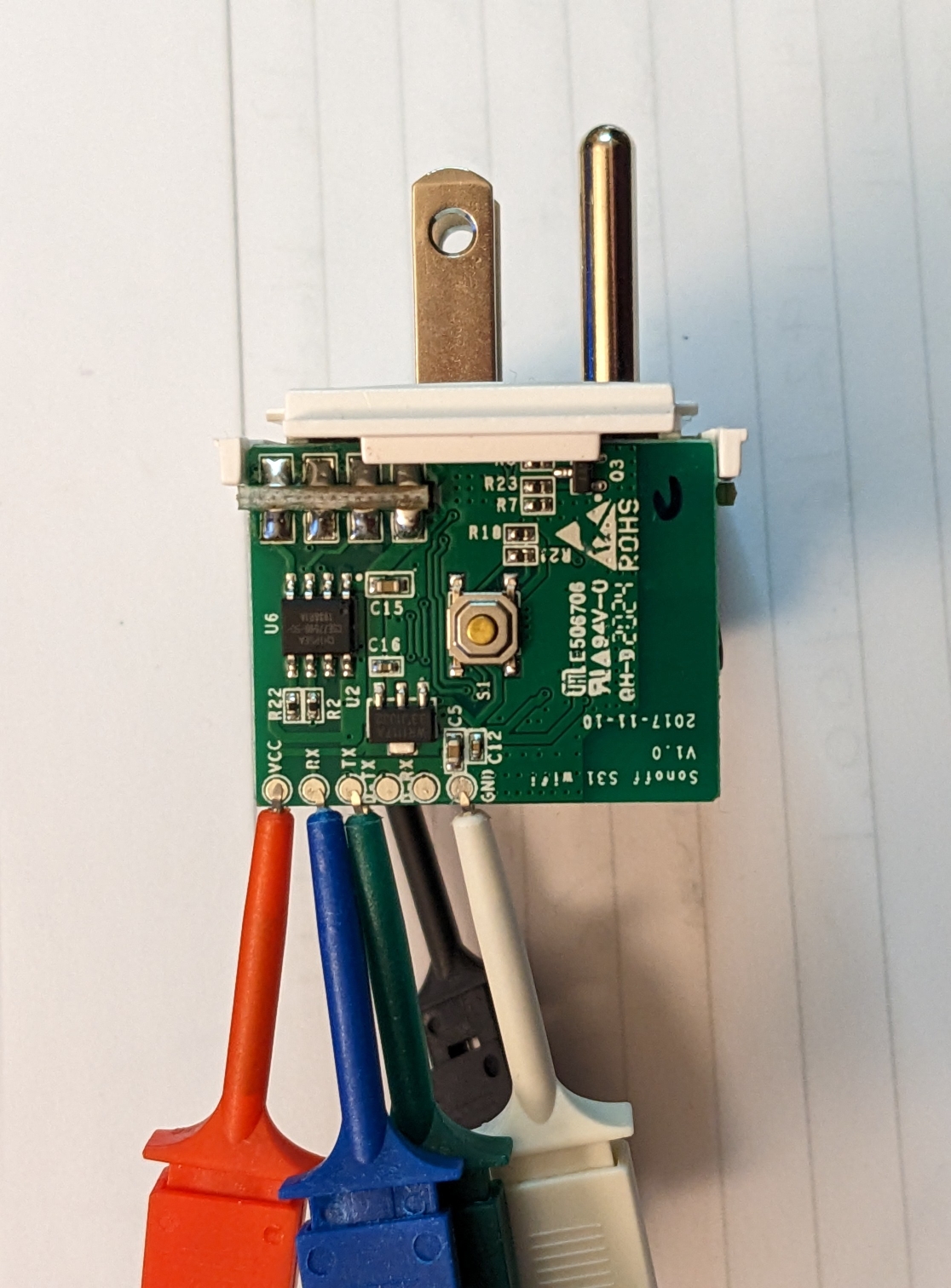
Sadly, I never posted any notes on the Sonoff products. Long ago I ordered a set of S31 outlets and B1 lamps. Both of which I reflashed with espurna. The notes on how to flash tasmota are helpful here, too. I found a quick tutorial on flashing with a Raspberry Pi in their docs. In todays world you might need to use pip3 instead of pip to install esptool. Tinkerman has posted lots of great details for the S31.

NEVER connect the S31 to mains power when flashing. For the S31 the connections to the Pi are very simpleSonoff S31 connections Raspberry Pi connections:

    S31 Pin - Pi Pin
    Vcc     - #1 (3.3vdc) - do not connect yet
    RX      - #8 (TX)
    TX      - #10 (RX)
    GND     - #39 (Ground)

Once you have the wiring ready you can setup the Pi – make sure you have esptool installed. If not sudo pip3 install esptool should handle it. You can then use raspi-config -> InterfaceOptions -> Serial to say No to shell on the serial port and Yes to Serial hardware.

The S31 will enter loader mode if you hold down the button, connect Vcc and continue holding the button for 10 seconds. You are now ready to actually flash the device(I was using an older Pi 2):

esptool.py --port /dev/ttyAMA0 erase_flash
esptool.py --port /dev/ttyAMA0 write_flash -fm dout 0x0 /path/to/downloaded/image

If you are using a Pi 3 or 4 replace ttyAMA0 with ttyS0.

The bad news is the Sonoff B1 is no longer made and their replacement uses a different chip and is not re-flashable. For the B1 lamps I have MQTT control after reflashing is awesome. MQTT make the integration with Openhab super easy. If you happen to come across these at a good price then the flashing instructions at the Tasmota site are very helpful.

5/30/2022

Updates and a new RTL-SDR

Filed under: Home Automation,RTL-SDR — Tags: , — taing @ 5:53 pm

Time for some updates and to add the new RadarBox 978 MHz radio. The system is still Raspian based on Buster. Keep in mind the initially the RTL-SDR for ads-b data is device 1(RTL2832U) and the weather station data is on device 0(RTL2838UHIDIR).

I’ll take these things somewhat in the order originally installed. readsb(our option over the other dump1090 alternatives) can be updated using the same bash script that was used for the install. Be sure to keep your current /etc/default/readsb file.

sudo bash -c "$(wget -O - https://github.com/wiedehopf/adsb-scripts/raw/master/readsb-install.sh)"

tar1090(an improved web page to display your data) can be updated much like readsb using the original install script.

sudo bash -c "$(wget -nv -O - https://github.com/wiedehopf/tar1090/raw/master/install.sh)"

FlightAware is updated from your site’s My ADS-B Stats page. Once on your stats page, click on the gear and choose update.

Instruction for updating ADSBexchange can be found on their page. The short answer is a bit of command line:

ccurl -L -o /tmp/axstats.sh https://www.adsbexchange.com/stats.sh
sudo bash /tmp/axupdate.sh

FlightRadar24 should update from its repository with apt-get.

Updating graphs1090 is once again as simple as running the original install script again.

sudo bash -c "$(curl -L -o - https://github.com/wiedehopf/graphs1090/raw/master/install.sh)"

I found nothing on the RadarBox site regarding updates so I left it alone for now.

At this point everything should work as before with ADSBexchange, FlightAware, FlightRadar24 and RadarBox all still working.

Now it is time to update the serial numbers on the dongles, add the new 978MHz dongle and update the existing config files to work with that info. I used the notes at dump978-fa install instructions to set the serial numbers of the dongles. The RadarBox flightstick instructions also show how to update the serial numbers. I also updated /etc/rtl_433/rtl_433.conf to point to my new device with serial number 433(rtl_eeprom -s 433) for the LaCrosse Weather Station.

I then continued to follow the dump978 instructions.

sudo apt update
sudo apt install -y dump978-fa
sudo sed -i -e 's/RECEIVER_OPTIONS.*/RECEIVER_OPTIONS="--sdr-gain 43.9 --sdr driver=rtlsdr,serial=978 --format CS8"/' /etc/default/dump978-fa
sudo systemctl restart dump978-fa

Then a quick install of the ADS-B exchange UAT/978 feed client following the github instructions.

sudo bash -c "$(wget -q -O - https://raw.githubusercontent.com/adsbxchange/adsbexchange-978/master/install.sh)"

A quick edit to /etc/rbfeeder.ini to enable UAT/978MHz and a reboot and we are in business.

http://<pi-ip>/tar1090/
http://<pi-ip>/ax978/
http://<pi-ip>/radar/
http://<pi-ip>/graphs1090/
http://<pi-ip>:8754/

https://flightaware.com/adsb/stats/user/xxx
https://www.adsbexchange.com/myip/
https://www.flightradar24.com/account/feed-stats/?id=xxxxx
https://www.radarbox.com/stations/xxxxxx

12/29/2020

DDC and CEC and more TV control

Filed under: Home Automation — taing @ 10:54 am

The quest to control the TVs and monitors continues. One promising option is DDC/C control. I was able to install ddcutil: sudo apt-get install ddcutil. For the older Acer units with Nvidia Ion graphics I was able to retrieve EDID but was unable to detect DDC.

The ddcutil website suggested adding the following in /etc/modprobe.d/nvidia-ddc :

options nvidia NVreg_RegistryDwords=RMUseSwI2c=0x01;RMI2cSpeed=100

I found that for the GeForce GT 710 machine this helped but not for the Acer with Ion graphics. Unfortunately, the Samsung T24C550 TV only seems to support a limits subset of DDC commands.

Next up was ddccontrol. After installing, it wasn’t able to detect DDC on the Acer with Ion but was more successful of the GeForce system. Unfortunately, there was no entry for the Samsung in the ddccontrol database so only generic commands appear to be available.

It is worth noting that even on the GeForce system once the monitor went to sleep it wasn’t detected at all by either ddcutil or ddccontrol.

Further notes on using ddcutil without being root can be found at https://frdmtoplay.com/using-ddccontrol-as-a-non-root-user/#:~:text=ddcutil%20is%20a%20CLI%20based,is%20not%20’officially’%20supported. This really comes down to adding users to the i2cusers group.

CEC

CEC is another option for controlling HDMI devices. While CEC can be used with a variety of devices it is especially useful on the Raspberry Pi. Again, unfortunately it is not supported by most Nvidia cards but is reported to work with the Nvidia Shield.

Your first step will be to install cec-utils: sudo apt-get install cec-utils. Hopefully a scan will turn up your device.

 echo "scan" | cec-client -s -d 1

If it does not it is worth looking into cec-util from the v4l-utils package. You may find to need to install/create the drivers for /dev/cec0.

For my Samsung, CEC was not enabled by default. Samsung refers to CEC as Anynet+. It can be enabled in the Service Menu. To enter the service menu, with the power to the TV off press MUTE 1 8 2 POWER quickly on the remote. Other Samsung units use INFO MENU MUTE POWER for the service menu.

I found some good info on using Raspberry Pi with CEC and a variety of devices at https://www.raspberrypi.org/forums/viewtopic.php?f=35&t=15593&p=158409&hilit=cec_client#p158409.

An no discussion of using CEC would be complete without mentioning CEC-O-Matic. This website allows you to “build your own” CEC commands.

Samsung – In Depth

There is lots of in depth info on Samsung TVs and firmware at https://wiki.samygo.tv/index.php?title=This_is_the_first_document_you_have_to_read.

Vizio Smartcast

If you have a Vizio with Smartcast there is a bit of detective work shown on github.

12/20/2020

Roku Remote Control

Filed under: General,Home Automation,RTL-SDR — taing @ 10:36 pm

Back in April I mentioned adding some Roku remote control. At this point I’m thinking more javascript than Python.

Roku has a good External Control Protocol reference online.

Sending commands

Unfortunately, the Roku API will not accept Cross Origin Request. This is not an issue if communicating from Node or Python but from the browser using xhr or fetch() you will get CORS errors. When sending POST for button presses you don’t care about the response for a “mode:’no-cors’ ” will work.

let resp = await fetch("http://roku-ip:8060/keypress/play", {method:'POST', mode:'no-cors'})

For the GET for status from the browser one option is a “proxy” add the “Access-Control-Allow-Origin” header. Borrowing the idea from https://medium.com/gitignore/building-a-roku-remote-web-app-1c0db0056be4 we set our Apache web server.

sudo pico /etc/apache2/apache2.conf to edit the config file and add the following lines:

<Location /roku>
    ProxyPass "http://roku-ip:8060/"
    ProxyPassReverse "/" 
    Header add "Access-Control-Allow-Origin" "*"
</Location>

You will need to have several modules loaded in Apache for this to work: headers and proxy_http. This can be done with:

sudo a2enmod proxy_http
sudo a2enmod headers
sudo systemctl restart apache2

Deep Links

A very important link for launching directly into netflix content is https://unogs.com/search/. From this site you can find the contentid for much of the netflix content.

This allows for directly linking to content with something like:

curl -d '' "http://roku-ip:8060/launch/12?contentid=70136120&mediatype=series"

This is a simple POST to the URL with no body.

The folks at unofficial Netflix online Global Search also provide an API.

12/13/2020

IR Blaster

Filed under: General,Home Automation,RTL-SDR — taing @ 3:30 pm

We get started with the Sparkfun WRL-15031. The hook-up guide is a good place to start. I am using the  IR Controller ESP8266 firmware.

I don’t have PlatformIO installed so I used the standard Arduino IDE. This was my first time with the ESP8266 so I needed to add the ESP8266 Arduino Core. In the current Arduino IDE this can be done by adding https://arduino.esp8266.com/stable/package_esp8266com_index.json to  the File>Preferences>Additional Boards Manager URLs field of the Arduino IDE. Then using the Board Manager from the Tools > Board menu you can install the esp8266 platform.

Once you have the IDE installed and the board set to Generic ESP8266 you need to make sure you have some libraries installed. ESP8266WebServer, ESP8266WiFi and WiFiManager but you may need to install ArduinoJson, Time and IRremoteESP8266.

It’s time to load the sketch, compile and upload.

The key here is to make sure you set the IO pin definitions correctly.

const int pinr1 = 13; // Receiving pin
const int pins1 = 4; // Transmitting preset 1
const int pins2 = 12; // Transmitting preset 2
const int pins3 = 12; // Transmitting preset 3
const int pins4 = 12; // Transmitting preset 4
const int configpin = 0; // Reset Pin
const int ledpin = 5;

I changed getExternalIP = false; and removed the user_id related and Alex integration code. I set ntpServerName to my internal NTP server. I changed the ntp sync time from 5 minutes to 12 hours near the end of the setup() function: setSyncInterval(43200);.

Once the code is compiled and loaded some testing is needed. On the initial run the ESP will be in AP mode with a SSID of IR Controller Configuration. You can connect and set access point info, hostname, static IP, subnet mask, port, default gateway and passcode.

Once you’re able to connect it is time to find some IR codes. There is a bit of good info in the Tasmota IR page. I found Sony DVD player remotes and some of the IR controlled LED votive candles. There is also good info for Samsung and Vizio TVs online. The codes from http://remotecentral.com often need to be manipulated before they are compatible with the ESP IR library. I created a Excel spreadsheet with worksheets for Vizio, Sony and Samsung.

Once we have the codes we can start controlling things from the web. For example:

http://someip:port/msg=msg?code=E0E040BF:SAMSUNG:32&pass=1234&simple=1

will send a power on/off command of 32 bits in SAMSUNG format. After testing a bit of this I created a simple webpage to send a variety of codes.

There is more Arduino IR blaster info at Ken Shirriff’s blogpost 1 and post 2. For more info on Sony codes refer to https://www.sbprojects.net/knowledge/ir/sirc.php and http://www.hifi-remote.com/sony/.

For the record: Toshiba remote: SE-R0047, Vivio Remote unmarked, Sony Remote RMT-B119A, JVC Remote: RM-S212U.

12/5/2020

screen at startup

Filed under: General,Home Automation,RTL-SDR — taing @ 11:33 pm

Sometimes it would be nice to have screen start a detached session at start-up. This isn’t complicated. There are two steps. The first is to create a script to be run in the detached session and make it executable. We’ll call it start.sh.

pico start.sh
chmod +x start.sh

The second is to edit /etc/rc.local to have the script run inside screen at start-up. Add the following line before the exit 0 line.

su - pi -c "screen -dm -S pistartup ~/start.sh"

That’s all there is to it. I found notes on this at https://coderwall.com/p/quflrg/run-a-script-on-startup-in-a-detached-screen-on-a-raspberry-pi.

6/22/2020

Dust – adding the SDS011

Filed under: General,Home Automation — taing @ 11:23 am

A SDS011 dust sensor(datasheet and communications protocol) from Amazon has been added to openhab. There is lots of good info online describing the sensor performance and Arduino(1, 2), ESP32(1, 2) and Raspberry Pi(1, 2, 3, 4, 5) setup. There is even PC based software for testing.

Nettigo has a interesting article on using the sensor with a heater inline to improve performance in high humidity. They use a Sensirion SHT30 to automatically drive a MOSFET to trigger a PTC Heating element.

One of the nice things about the package as purchased is it comes with connectors and an USB/serial adapter to allow for connections using USB, TTL serial or i2c.

In the end, it was simplest to use the brand new Openhab plugin binding. The binding reports both 2.5 and 10 µg/m³. The binding allows for easy setup of reporting mode allowing the sensor to pretty much manage itself. For reporting mode, a reporting interval is set. The unit will wake up every interval and measure for 30 seconds then sleep for interval minus 30 seconds.

Since plugging the sensor directly into the openhab server in the basement wasn’t going to be very useful a modified version of the same method used to remote the Z-Wave dongle was used. This required installing ser2net on the Pi with the sensor and setting the correct comm parameters(9600 8N1) and making copies of /etc/default/socat.conf(updated with the proper device name and IP address of the Pi with the sensor) and /etc/init.d/socat (updated to point to unique .log and .pid files and the new .conf file).

6/21/2020

Update to LaCrosse weather

Filed under: General,Home Automation,RTL-SDR — taing @ 5:51 pm

While these updates were made a while ago they weren’t documented. In the original post on the LaCrosse Weather station, rtl_433 sends mqtt data to our openhab server. On github we found a simple means to get rtl_433 to run as a service.

The core is to update /etc/rtl_433/rtl_433.conf. There is a sample file at conf/rtl_433.example.conf. Most important is the output mqtt... line for example:

output mqtt://jtk-openhab,devices=rtl_433/garage[/model]

If the Pi has multiple dongles you will also need to confirm the device line. Then create /etc/systemd/system/rtl_433-mqtt.service:

[Unit]
Description=rtl_433 to MQTT publisher
After=network.target
[Service]
ExecStart=/usr/local/bin/rtl_433
Restart=always
RestartSec=5
[Install]
WantedBy=multi-user.target

Enable the service with systemctl enable rtl_433-mqtt.service.

6/20/2020

Migration – a new server for openhab

Filed under: General,Home Automation — taing @ 3:39 pm

It was time to migrate the openhab installation from the Raspberry Pi 3B to the NUC.

Before leaving the Pi a full backup is required. openhab-cli backup name_of_zipped_backup. Details on the backup and restore process can be found in the openhab forums.

The installation starts with a fresh Debian Buster(10.4) console only install. Openhabian was added from git following the guide at https://www.openhab.org/docs/installation/openhabian.html.

sudo apt-get install git screen curl gnupg
sudo git clone https://github.com/openhab/openhabian.git /opt/openhabian
sudo ln -s /opt/openhabian/openhabian-setup.sh /usr/local/bin/openhabian-config

The optional Influx db for persistence and Grafana for graphs were added from the openhabian-config tool. Chronograf 1.8 was also added manually ( sudo apt-get install chronograf ) since Influx after v1.3 doesn’t support the web console anymore. Note this is from the Influx repo which is added by the openhabian-setup tool.

At this point:
Openhab web interface -> http://your_ip:8080
Openhab console (ssh) -> your_ip:8101
Influx web admin (chronograf) -> http://your_ip:8888
Grafana -> http://your_ip:3000

Hopefully, at this point it’s time to restore the backup made earlier on the Pi: openhab-cli restore name_of_zipped_backup

Possible Issues

To resolve the issue of the openhab repo not being properly signed refer to the discussion in the openhab forums. You will need to execute:

wget -qO - 'https://bintray.com/user/downloadSubjectPublicKey?username=openhab' | sudo apt-key <strong>add</strong> -

If you encounter errors in the log file regarding RestDocs, for example, “ERROR] [core.karaf.internal.FeatureInstaller] - Failed installing ‘openhab-misc-restdocs’“, refer to the discussion in the forums. The secret is the second set of config files at /var/lib/openhab2/config/org/openhab/addons.config.

If you encounter broken graphs in the Openhab UI with error messages similar to [WARN ] [org.eclipse.jetty.server.HttpChannel] - /chart
java.lang.Error: Probable fatal error:No fonts found
refer to the discussion in the forums. The trick here is to install fontconfig for 32 bit arch even on a 64 bit machine: sudo apt-get install fontconfig:i386. A restart of the openhab service will be required after installing fontconfig: sudo systemctl restart openhab.service.

Remote Z-Wave

One of the main reasons openhab had stayed on the Pi so long was the location of the Pi and the Aeon Labs DSA02203-ZWUS Z-Wave Z-Stick Series 2 USB Dongle. This dongle creates /dev/ttyUSB0 for the z-wave binding. Our solution was to leave the Pi in place with the dongle and handle the serial port connection over Ethernet to the NUC. ser2net gets installed on the machine with the dongle. socat gets installed and run as a service on the openhab server machine. There is a great discussion on the in the openhab forums.

On the Pi:
sudo apt-get install ser2net
pico /etc/ser2net.conf
3333:raw:0:/dev/ttyUSB0:115200 8DATABITS NONE 1STOPBIT
On the NUC:
sudo apt-get install socat
git clone https://github.com/asaif/socat-init.git
sudo cp socat-init/socat /etc/init.d/
sudo chmod +x /etc/init.d/socat
sudo update-rc.d socat defaults
sudo cp socat-init/defaults/socat.conf /etc/default/

sudo nano /etc/default/socat.conf
OPTIONS="pty,link=/dev/ttyUSB0,raw,user=openhab,group=dialout,mode=777 tcp:ip_of_the_pi:3333"
sudo service socat restart

This will create /dev/ttyUSB0 on the NUC which looks like a serial device to the z-wav binding.

Final Steps

The final steps were to make sure everything that was pointing the to Pi was now pointing to the NUC.

The RFM69HCW 915MHz radio on the original openhab Pi remained in place listening to the Moteinos and sending mqtt but needed to have the destination updated. This required recompiling Gateway.c. Somehow the appropriate libraries weren’t already on the Pi for this: sudo apt-get install libmosquitto-dev libmosquittopp-dev. The recompile then when fine: g++ Gateway.c rfm69.cpp -o Gateway -lwiringPi -lmosquitto -DRASPBERRY -DDEBUG.

The code on the Pi sending outside temperature and humidity via mqtt from the am2315 i2c sensor needed to be recompiled to send to the proper destination: gcc piGateway.c -o piGateway -lwiringPi -lmosquitto -lam2315 -DRASPBERRY -DDEBUG.

The Pi running the Weather Alert / SAME code needed to have the destination address updated. This is a simple change to the mqtt command line parameter in the script. The same Pi also runs the Seneye aquarium monitor code which needed an edit in suddriver.py to update the mqtt destination.

The Pi running rtl_433 for the LaCrosse weather station integration required an update to rtl_433.conf to point the mqtt data to the new destination. The same Pi also runs the as3935 Lightning detector. A quick modification to the python script to fix the mqtt destination got this back online.

5/18/2020

Earthquake

Filed under: General,Home Automation — taing @ 4:50 pm

An article on the Raspberry Shake got me looking for more on earthquake sensors. I found the Omron D7S. Datasheet here.

The chip can be found at both Mouser and Digikey. It is a small SMT mountable PCB that communicates via i2c. The datasheet provides little info on actually programming the device. Googling about found two libraries that helped shed some light on things.

First, from Omron, a python library on github. The platform of choice is a Pi Zero W with Rasbian Buster Lite. To get started, install git, i2c-tools, python3-smbus, and python3-rp-gpio. Clone the repo and the software is ready.

Connecting the sensor to the Pi only needed four wires – 3.3v, gnd, SDA, SCL. 10k pull-up resistors are used for SDA and SCL. A 10k pull-up was also added for the sensor “settings” pin. Both Vcc and both Ground pins on the sensor need to be wired.

  • Pi pin 1 – Vcc to Sensor pins 1 & 9
  • Pi pin 1 – Vcc to 10K pullup resistors to sensor pins 4, 5 & 7
  • Pi pin 9 – Ground to Sensor pin 6 & 10
  • Pi pin 3 – SDA to sensor pin 5
  • Pi pin 5 – SCL to sensor pin 4

Sensor pins 2 and 3 provide optional interrupts. Pin 3 goes low when a quake is in happening. Pin 2 goes low to signal suggested shutdown due to expected significant damage. These pins are not used in this setup.

sudo i2cdetect -y 1 showed the chip at address 0x55. sudo python3 sample_d7s ran as advertised.

I added a few line of code to have the output go to a Google Sheet and set the unit up in the basement. Details on how this works can be found in an earlier post.

The second library is for Arduino. It appears to provide much greater detail on the registers and parameters on the chip but I have not tested it.

An additional article on How to Make an Earthquake Alarm is a alternative approach.

The chip measures quake intensity not magnitude. The measurement correlates strongly with the Japan Meteorological Agency seismic intensity scale. A discussion on various seismic intensity scales can be found here or copied here.

Omron shared a more detailed datasheet.

Older Posts »

Powered by WordPress